Open Pcb File Type
PCB design output is the files required by the manufacturers for designing the PCB. While working on a PCB layout, you edit a file that is exclusive to your CAD software. It’s not a universal file format, and the information it uses is unnecessary to the manufacturer. This is why you need to generate a different sort of file when you convert the schematic into a physical circuit board. Inside almost every electronic device is a PCB onto which the components are mechanically and electrically connected by soldering. PCB design uses a computer-aided design (CAD) system. To physically realize the design, the computerized design information must be transferred to a photolithographic computer-aided manufacturing (CAM) system. Since the CAD and CAM systems are generally produced by different companies, they have to agree on a CAD-to-CAM data exchange format to transfer the data.
What Is A Pcb File

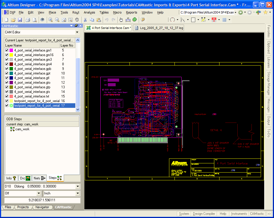
ODB++
Open PCB File To open PCB file you need to find an application which works with that kind of file. PCB file extension is used by operating systems to recognize files with content of type PCB. Here is some information which will get you started. They are similar to plugins, as they add user-modified functions to EAGLE. ULPs use the.ULP file extension and are available for download on the Autodesk EAGLE website. Autodesk EAGLE is a useful PCB CAD application. It provides tools to design your PCB and supports ULP functionality.

As we discussed earlier CAD-to-CAM data exchange format, ODB++ is such a format. When ODB++ is used, its data is stored in a hierarchy of files and file folders. While being transferred, designers will use common operating system commands that retain the hierarchy structure by fusing all of the data into one compressed file. ODB++ allows designers and manufacturers to transfer more than just the standard layer artwork and drill data. This is possible because of its hierarchical nature. ODB++’s unique file structure allows for large amounts of additional data to be included in a single file, including the material stack-up, bill of materials, and component placement, as well as dimension and fabrication data. ODB++ can be accessed through most PCB design programs (Expedition, PADS, Allegro), making it almost a universal format throughout PCB manufacturing (except Eagle).


IPC-2581
IPC-2581 is a generic standard for PCB assembly and manufacturing description data and transfer methodology. Developed in 2004 by IPC, IPC-2581 is again like other two is used for transferring information between a PCB designer and a manufacturer or assembler. For almost every step in the process flow, IPC-2581 offers a guideline to help companies ensure superior manufacturability, quality, reliability and consistency in electronics assemblies built for their products.

Gerber Files
Pcb File Types
The most widely used file format for PCB manufacturing is called Gerber. When manufacturers request “Gerbers” or “Gerber files,” they basically look for ASCII files that contain Gerber-formatted data. These are actually “CNC” files. They drive the photoplotter to create the film that is used to expose each conductor layer in the board. A Gerber file has no idea about design rules, net connectivity, or component libraries; it is simply two-dimensional artwork that indicates where the manufacturing equipment will place copper, solder mask, or silkscreen. One Gerber file provides information for one PCB feature on one layer. Thus, if you have a two-layer board and each side has Gerber files copper, solder mask, and silkscreen, you will need six Gerber files.